


Concentrated Energy Automotive H5V Hydraulic ABS Maintenance Guide
H5V Hydraulic ABS Maintenance Guide
The ABS of Suzhou Jinlong H5V is the third generation hydraulic ABS product of Juneng Company, and its ECU model is JN244-3. The main chip of ECU has powerful computing and digital signal processing functions, as well as rich peripheral interfaces.
The JN244-3 ABS has a K-line diagnostic function that meets the KWP2000 international standard.
After connecting with ABS using a K-line diagnostic instrument, ECU information such as model, software version number, production date, batch number, and number can be easily read out. When using the diagnostic function, the current faults and past stored faults of the ECU can be read out.
After using the offline detection equipment to connect to ABS through the K line, it can also detect whether the ABS harness connection and brake pipeline connection of the entire vehicle are correct, whether the signal of the wheel speed sensor is normal, whether the ABS warning light function is normal, whether the hydraulic modulator function is normal, and whether the vacuum filling of brake fluid is carried out.
The ABS of the H5V vehicle uses Hall wheel speed sensors, which allow for a large gap (the distance between the sensor head and the gear ring). The test shows that there is still a signal when the gap is 2-3mm, overcoming the disadvantage of traditional electromagnetic induction sensors that have extremely strict clearance requirements.
1. Composition of hydraulic ABS
Hydraulic ABS is mainly composed of gear rings, wheel speed sensors, electronic controllers (ECU), valve bodies (pressure regulators), pump motors, and wiring harnesses. Among these components, the ECU, valve body, and motor are the most closely connected, forming the hydraulic ABS assembly. The ECU is connected to the valve body through four screws, allowing the wire package in the ECU to control the solenoid valve on the valve body to complete the function of pipeline pressure regulation.
The following is a schematic diagram of circuit and pipeline connections:
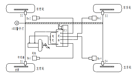
S1, S2, S3, and S4 in the figure are wheel speed sensors. The ABS of the H5V vehicle uses Hall wheel speed sensors, which allow for a large gap (the distance between the sensor head and the gear ring). The test shows that there is still a signal when the gap is 2-3mm, overcoming the disadvantage of traditional electromagnetic induction sensors that have extremely strict clearance requirements. However, it is still required that the gap change of the gear ring after one revolution should not be too large, otherwise it will cause fluctuations in wheel speed.
2 Pipeline connection
The pipeline connection of the H5V vehicle is an X-type, also cross or diagonal. The pipeline connection is shown in the following figure:
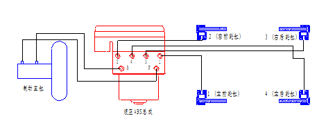
In the figure, F and R are the oil inlet holes of the ABS assembly, which are respectively connected to the two oil outlet holes of the brake master cylinder. 1. 2, 3, and 4 are the oil outlet holes of the ABS assembly, which are respectively connected to the left front wheel cylinder, right front wheel cylinder, right rear wheel cylinder, and left rear wheel cylinder.
3 circuit connections
The following is the circuit connection diagram of H5V hydraulic ABS:
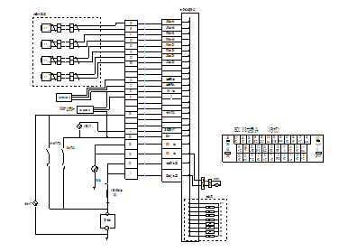
In the figure, terminal 25 is the solenoid valve power supply; Terminal 1 is the power supply for the return pump motor; Terminal 32 is the ECU working power supply; Terminal 17 (RRS) and terminal 1 (RRG) are the signals of the right rear sensor; Terminal 18 (RFS) and terminal 2 (RFG) represent the front right sensor signals; Terminal 10 (LRS) and terminal 3 (LRG) are the left rear sensor signals; Terminal 11 (LFS) and terminal 4 (LFG) are the left front sensor signals; Terminal 12 (BRK) is the brake light signal; Terminal 16 (LMP) is the ABS lamp driver circuit signal; Terminals 13 (TXD), 14 (GND), and 15 (RXD) are RS232 data communication interfaces; Terminals 8 (GND) and 9 (GND) are common ground (power negative).
4. Normal status of ABS after pipeline and circuit connections
4.1 Normal value measured from the ECU 38 core plug without plugging in the ECU
·Positive end of ECU working power supply (32 pins): 0V when the ignition switch is turned off; When the ignition switch is turned on, it is between 10V and 15V.
·ECU working power supply negative terminal (13 pins, 38 pins): connected to the negative terminal of the car battery (0V).
·Electromagnetic valve power supply (25 pin): 10V~15V.
·Pump motor power supply (1 pin): 10V~15V.
·Brake light signal (30 feet): When the brake pedal is not pressed, it is 0V, and when the brake pedal is pressed, it is 10V to 15V.
·ABS light driver circuit signal (4 pins):
When the ignition switch is turned off, it is 0V, and the ABS light on the dashboard does not light up;
When the ignition switch is turned on>5V, the ABS light on the dashboard lights up; Short circuit pin 4 with a wire to pin 13, and the ABS light will turn off. (This test is used to check if the ABS lamp driver circuit is working properly)
The normal operation of the Hall sensor can be checked using the following methods:
Connect an 8-10V DC power supply and a voltmeter to the 100 Ω resistance, probe A and probe B as shown in the figure below:
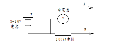
·Check the left front sensor:
Probe A is inserted into pin 34 of the ECU plug, and probe B is inserted into pin 22.
Under normal circumstances, the reading of the voltmeter is about 0.7V (low level) or 1.5V (high level). Turning the left front wheel can see that the reading of the voltmeter constantly jumps between low level and high level.
If the voltmeter reads 0V, the sensor circuit is disconnected. If the reading of the voltmeter is close to the supply voltage, the Hall sensor is connected reversely.
·Check the front right sensor:
Probe A is inserted into pin 18 of the ECU plug, and probe B is inserted into pin 6. The method is the same as above.
·Check the rear right sensor:
Probe A is inserted into pin 19 of the ECU plug, and probe B is inserted into pin 31. The method is the same as above.
·Check the left rear sensor:
Probe A is inserted into pin 33 of the ECU plug, and probe B is inserted into pin 20. The method is the same as above.
4.2 Normal state of inserting ECU
Turn on the ignition switch in the parking state, and the ABS light on the dashboard will light up for 3 seconds before going out. In a quiet environment within this range, the sound of detecting the solenoid valve and pump motor can be heard.
During the process of starting the vehicle at a speed of 0-20 km/h, the ABS on the dashboard remains off, indicating that the ABS is working normally without any faults.
Regardless of whether parking or driving, as long as the ABS light remains on (referred to as permanently on) or flashing, it indicates a malfunction.
Fault Flashing Mode of 5 Accumulated Energy ABS
The fault flash code method of Juneng ABS is an improvement on the traditional two digit flash code method. There are two improvements: firstly, changing manual code reading to automatic code reading, simplifying operation; The second is to change the two digit flashing code to a one digit flashing code, making code reading fast. This method is called the "automatic single flashing code" method, and it arranges the fault category and location as follows:
Use the ABS light to "flash quickly" (one on and one off for 0.5 seconds, flashing quickly) to indicate a sensor type fault.
Flashing 1 indicates a malfunction of the left front sensor
Flashing 2 indicates a fault with the right front sensor
Flashing 3 indicates a fault with the right rear sensor
Flashing 4 indicates a fault with the left rear sensor
Use the ABS light "slow flashing" (one on and one off for 1.5 seconds, flashing slowly) to indicate a regulator type malfunction.
"Slow flashing 1" indicates front left adjuster failure
"Slow flashing 2" indicates that the front right adjuster is faulty
"Slow flashing 3" indicates that the right rear regulator is faulty
"Slow flashing 4" indicates that the rear left adjuster is faulty
Use the ABS light "flash 5" to indicate a motor fault in the hydraulic ABS.
Use the ABS light "flash 7" to indicate a power failure.
After flashing the fault code for 5 cycles, the ABS light "remains on" (continuously on, not flashing), indicating the current existence of the fault. Careful driving and timely repair are required.
From the above, it can be seen that "fast flashing" indicates a sensor fault, "slow flashing" indicates a regulator fault, and the number of flashes indicates the fault location. 1-4 respectively represent: left front, right front, right rear, and left rear; Flashing 5 indicates motor failure; Flash 7 indicates a power failure; The "long light" indicates an ECU or other malfunction. You don't need to check the fault code table to know it's

In the figure, fast flashing: T1=T2=0.25s, T3=1.2s, slow flashing: T4=T5=0.75s, T6=2.4s
6. Troubleshooting ABS faults based on flashing codes
6.1 Parking status fault
If the ABS light flashes during parking, troubleshoot according to Table 1:
Table 1
| Blinking mode | Fault location and cause | Troubleshooting method |
| Flash 1 | Left front sensor disconnected | Check if the sensor connector is loose and if the connection wire from the sensor connector to the ECU plug is disconnected. If there are no loose connectors or disconnected connecting wires, refer to the method in section 4.1 to determine whether the Hall sensor function is normal. If not, replace the sensor. |
| Flash 2 | Right front sensor disconnected | |
| Flash 3 | Right rear sensor disconnected | |
| Flash 4 | Left rear sensor disconnected | |
| Slow flashing 1 | Left front solenoid valve disconnected | Because the solenoid valve wire is wrapped inside the ECU, replacing the ECU is sufficient. |
| Slow flashing 2 | Right front solenoid valve disconnected | |
| Slow flashing 3 | Right rear solenoid valve disconnected | |
| Slow flashing 4 | Left rear solenoid valve disconnected | |
| Slow flashing 5 | Motor not connected or damaged | Check the contact condition of the motor plug and supply 12V voltage to the motor from the plug. If it does not rotate, replace the motor or ABS assembly. |
| Slow flashing 7 | Abnormal power supply | Check the ABS fuse (30A) and replace it if it is broken; Check if the power supply voltage deviates from the normal value. |
| Not lit | ABS light damaged | Replace the ABS light on the dashboard |
| ABS light driver damaged | Replace ABS light driver |
6.2 Driving status faults
There are no faults before the vehicle starts, but when the vehicle speed exceeds 15Km/h after starting, the ABS light flashes and the fault is eliminated according to Table 2:
Table 2
| Blinking mode | Fault location and cause | Troubleshooting method |
| Flash 1 | Left front sensor signal abnormal |
Check the fixation of the sensor and the installation clearance with the gear ring. If the installation is normal, refer to the method in section 4.1 to determine whether the Hall sensor function is normal. If it is not normal, replace the sensor.
|
| Flash 2 | Right front sensor signal abnormal | |
| Flash 3 | Right rear sensor signal abnormal | |
| Flash 4 | Left rear sensor signal abnormal |
7 shaped energy ABS computer diagnostic instrument
This type of fault diagnosis instrument can collect four wheel speed curves in real-time during driving and braking, providing the most powerful assistance for analyzing sensor signals. In addition, it can also be used to analyze whether the original vehicle's braking is normal and the braking effect of ABS.
7.1 Composition and connection of computer diagnostic equipment
The gathered energy ABS computer diagnostic instrument consists of a laptop, a dedicated data communication cable, and diagnostic software. A dedicated cable is used to connect the data interface on the ABS harness to the RS232 interface of the computer. If the laptop does not have an RS232 interface, connect it to the USB interface of the laptop through an RS232 to USB adapter cable. After starting the computer, execute the data collection application software (sc. exe) to enter the following data collection interface:
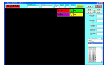
7.2 Check if the wheel speed sensor signal is normal
Before the car starts, enter the data collection interface. When the car starts, press the collection button to start collecting data. When the vehicle speed exceeds 30km/h, release the button to stop collecting data. At this point, the computer displays four curves of wheel speed from low to high, called the "wheel speed climb curve", as shown in the following figure:

Among the four curves, red represents the left front wheel, green represents the right front wheel, yellow represents the right rear wheel, and purple represents the left rear wheel.
The four wheel speed climb curves must be relatively smooth (gradually increasing without sudden changes) when the vehicle speed is above 10km/h. Otherwise, it indicates that the sensor signal is abnormal. It is necessary to check whether the sensor is installed properly and adjust the gap.
7.3 Testing the braking performance of ABS
After the car starts, maintain the speed at 55km/h, press the acquisition button while pressing the brake pedal, and release the button when the speed drops to zero. At this time, the computer displays four wheel speed fluctuation curves from high to low, called the "brake wheel speed curve", as shown in the following figure:
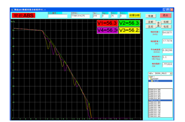
The braking wheel speed curve can accurately reflect the braking performance of ABS, and the small fluctuation of the wheel speed curve reflects the smooth and comfortable braking; The coaxial left and right wheel curves overlap most of the time, indicating that the left and right braking forces are balanced, do not deviate, and have good braking stability.
8. K-line diagnostic instrument
The ABS of Suzhou Jinlong H5V is the third generation hydraulic ABS product of Juneng Company, and its ECU model is JN244-3.
JN244-3 ABS has a K-line diagnostic function that meets the KWP2000 international standard.
After connecting with ABS using a K-line diagnostic instrument, ECU information such as model, software version number, production date, batch number, and number can be easily read out. When using the diagnostic function, the current faults and past stored faults of the ECU can be read out.
After using the offline detection equipment to connect to ABS through the K line, it can also detect whether the ABS harness connection and brake pipeline connection of the entire vehicle are correct, whether the signal of the wheel speed sensor is normal, whether the ABS warning light function is normal, whether the hydraulic modulator function is normal, and whether the vacuum filling of brake fluid is carried out.
For further details, please contact us
Consultation hotline:+86-13908307100, 13752990427
Office phone:+86 023 63115900, 63115950
Fax:+86-023-67881453
Website: www.jnabs.com
Email: jnabs@jnabs.com
Address: 25th floor, Qibo Building, No. 99 Jinyu Avenue, North New District, Chongqing.