


Accumulated Energy Automotive ABS User Manual (Air Brake System Part) Third Edition
catalogue
preface
1. Overview of Accumulated Energy ABS
2. JN 1xx FB Naming and Classification
3. JN 1xx FB working environment
4. Main technical parameters of JN 1xx FB
5. Composition of JN 1xx FB system
6. JN 1xx FB Installation and Debugging
7. JN 1xx FB fault display mode
8. JN 1xx FB Fault Diagnosis and Troubleshooting
9. ABS fault diagnosis interface and fault diagnosis instrument
10. Precautions for ABS use
Attachment 1: JN144FB-1 Wiring Diagram
Attachment 2: JN144FB-2 Wiring Diagram
Attachment 3: JN166FB-1 Wiring Diagram
Attachment 4: JN188FB-1 Wiring Diagram
Composition of JN 1xx FB system
The JN 1xx FB type ABS is an automotive anti lock braking system developed by Chongqing Juneng Automotive Technology Co., Ltd. based on the conditions of vehicles and roads in China, with independent intellectual property rights. Its key technology has obtained four national patents (patent number ZL 9 8 2 29255.4),
ZL 02 2 75676.0, ZL 02 3 55574.2 , ZL 02 2 75677.9 )。 The JN 1xx FB ABS product has passed the inspection by the National Automobile Quality Supervision and Inspection Center (Xiangfan) and meets the requirements of GB/T 13594-2003 "Anti lock Braking Performance and Test Methods for Motor Vehicles and Trailers".
This manual introduces the installation, use, and maintenance methods of the Juneng JN 1xx FB ABS, as well as the fault diagnosis and various precautions of the ABS.
1. Overview of Accumulated Energy ABS
When a car adopts emergency braking at high speeds or on slippery roads, once the wheels lock up, they will lose lateral adhesion and cause side slip, tail spin, and steering loss of control. This is one of the important reasons for traffic accidents.
Anti Lock Braking System (ABS), abbreviated as ABS, is a high-tech product widely used in developed countries today to improve vehicle braking performance and improve driving safety. Juneng Company has designed electronic controllers (ECUs) and pressure regulators based on the condition of vehicles in China. Its main components are made from world-renowned enterprise products, using mounting technology and three prevention treatment. During the braking process of vehicles equipped with ABS, the electronic controller (ECU) calculates parameters such as the vehicle's driving speed, deceleration, and road adhesion coefficient, and automatically adjusts the brake pipeline pressure of the four wheels through a pressure regulator to control the wheel slip rate in the optimal range, enabling the vehicle to achieve the best braking effect and stability; Braking on slippery roads or at high speeds can shorten the braking distance, and the direction can be controlled according to the driver's intention; In addition, it can also reduce tire wear and reduce the loss of roundness of the brake drum.
JN 1xx FB is an electronic controlled air brake system for anti lock braking of automobiles, suitable for various models using air brake systems. When the car is braking while in motion, vehicles equipped with ABS products will implement emergency braking to the maximum extent without skidding, tailspin, and directional control. The braking operation is simple and convenient. When implementing emergency braking on any road surface, just press the brake pedal.
2. JN 1xx FB Naming and Classification
The product name and classification of the "Juneng" ABS anti lock braking system are as follows:
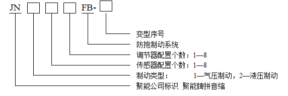
Example: JN14 4 FB-1 4 Sensor 4 Adjuster 1 Pneumatic Brake Anti lock Braking System
JN 2 4 4FB 4 sensor 4 regulator hydraulic brake anti lock brake system
3. JN 1xx FB working environment
Environmental temperature: electronic controller -40 ℃ -+85 ℃
Pressure regulator -40 ℃ -+85 ℃
Wheel speed sensor -40 ℃ -+200 ℃
Atmospheric pressure: 53--------106KPa
Relative humidity: ≤ 95% 25 ℃
4. Main technical parameters of JN 1xx FB
4.1 Working voltage range: Electronic controller DC 20-30V
Pressure regulator DC 20-28V
4.2 Electronic controller ECU static working current: ≤ 15mA
4.3 ECU maximum control current:
ABS fault warning light: white woven light 150 mA
LED 50 mA
Pressure regulator solenoid valve: 3A × eight
Retarder relay: 200mA
4.4 Wheel speed sensor signal input peak value: Vp ≥ 0.5V (sensor ring gear clearance ≤ 0.7 mm, 100Hz)
4.5 Wheel speed sensor resistance 1550 Ω ± 70 Ω
4.6 Pressure regulator solenoid valve resistance 15 Ω ± 0.5 Ω
5. Composition of JN 1xx FB system
The JN 1xx FB system is mainly composed of components such as gear rings, wheel speed sensors, electronic controllers (ECU), pressure regulators, ABS fault warning lights, wiring harnesses, and mounting brackets. The 4-channel ABS is shown in the following figure:

Figure 1 Installation diagram of JN 144 FB anti lock braking system
6. JN 1xx FB Installation and Debugging
6.1 Installation and debugging of gear ring
Technical requirements: The fit between the gear ring and the wheel hub should adopt H8/s7 (tight fit), and the end face runout of the gear ring should be ≤ 0.15mm after installation.
Installation method: Firstly, machine the shaft head or gear ring to ensure that the fit between the gear ring and the wheel hub meets the technical requirements. Then heat the gear ring in engine oil to 180 ± 10 ℃ and keep it warm for 10 minutes. Quickly place the thermally expanded gear ring on the machined shaft head, then rotate the gear ring 1 to 2 turns, and the gear ring will naturally be installed in place. The installation process of the gear ring can be lightly hit with a wooden hammer. It is strictly prohibited to use excessive force or other hard objects to avoid damaging the tooth surface of the gear ring or causing deformation of the gear ring. After the installation of the gear ring is completed, its installation fit with the shaft head is shown in the following figure:
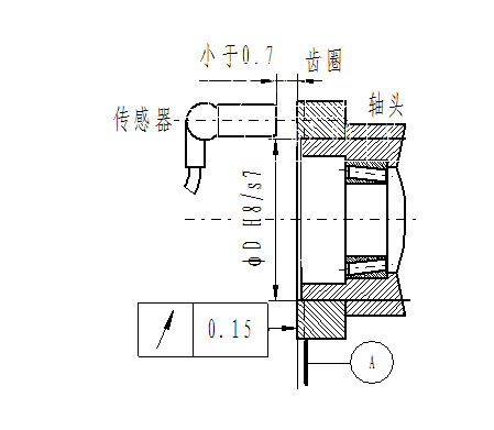 Figure 2 Installation diagram of sensor, gear ring, and shaft head fitting
6.2 Installation and Debugging of Wheel Speed Sensors
Normally, the installation of front axle sensors does not require a bracket. The sensor (bushing, clamp sleeve) can be inserted into the installation hole of the alignment gear ring, and the installation hole should be located on the brake plate or steering knuckle. But some vehicles also require brackets for the installation of front axle sensors.
The installation of sensors on the rear axle requires a sensor fixing bracket. The bracket should be installed in the stationary part of the shaft and should have sufficient rigidity and installation stability to reduce the impact of vehicle vibration. The sensor bracket varies depending on the vehicle and installation method, but the axial direction of the sensor should be perpendicular to the radial direction of the gear ring, and the maximum angle deviation should be less than 2 º. When installing, first apply lubricating grease to the jacket and install it into the bushing until the jacket flange contacts the bushing. Then insert the sensor coated with grease into the clamping sleeve and gently push the sensor until the end face of the sensor contacts the gear ring. After the wheel rotates, a gap naturally forms between the sensor and the gear ring. The installation of front and rear axle sensors is shown in Figure 3, Figure 4, and Figure 5.
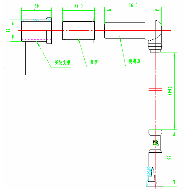
Figure 3 (Front), Installation Diagram of Rear Axle Wheel Speed Sensor, Jacket, and Bush
Note: The front axle sensor generally does not have an installation bracket, and the sensor bushing is inserted into the brake plate or steering knuckle installation hole.
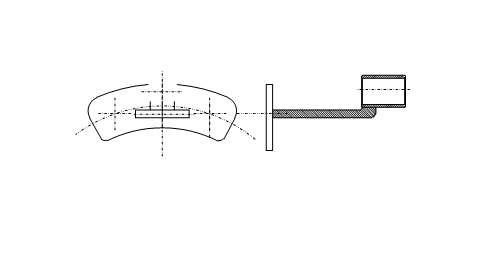
Figure 4 Rear sensor bracket of a certain vehicle model
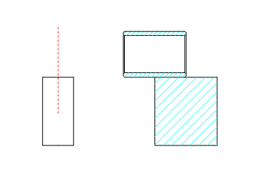
Figure 5 Sensor bracket for front and rear axles of a certain vehicle model
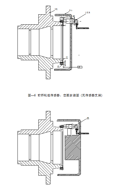
Figure 7 Installation diagram of rear axle wheel speed sensor and gear ring (sensor with bracket)
-
After the installation of the sensor is completed, the gap between it and the gear ring should be checked to see if it meets the requirements. The detection method is as follows
a) Measure the resistance at the output end of the sensor using a multimeter with a resistance (Ω) of 2K, and the value is 1.3 ± 0.1K; If it is not within this value range, the sensor should be replaced.
b) Rotate the wheel to a speed of 1 revolution per second, and use a multimeter to measure the output voltage of the sensor at 2V (AC). Measure the sensor output voltage to be ≥ 0.3V. If it is not within this value range, the gap between the sensor and the gear ring should be adjusted.
6.3 Installation and commissioning of pressure regulator
The pressure regulator should be installed between the wheel brake master cylinder and the brake cylinder, near the frame of the brake cylinder (), in order to control the pressure of the brake cylinder.
The connection method of the pipeline should be that the air inlet of the regulator should be connected to the quick release valve, and the air outlet should be connected to the brake wheel cylinder.
The installation method of the rear wheel pressure regulator is the same as the front wheel, but special attention should be paid to the service brake pipeline and the parking brake pipeline, and they should not be connected incorrectly. The external schematic diagram of its pressure regulator is shown in the following figure:
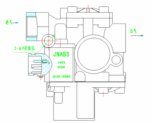
Figure 7 Installation diagram of pressure regulator
After installing the pressure regulator, the inlet and outlet joints should be carefully inspected for any leakage. If there is any leakage, it should be dealt with immediately until there is no leakage. After the installation of the pressure regulator, check whether the resistance of the solenoid valve of the regulator is normal (15 Ω ± 0.5). If the resistance value is not within this range, it indicates that the regulator cannot be used and should be replaced.
Note: The air inlet and outlet are clearly marked with arrows
6.4 Installation and debugging of electronic controller ECU
The electronic controller ECU should be installed in a place that is convenient for wiring harness layout, waterproof, moisture-proof, and high-temperature resistant, such as in the driver's cab or in the vehicle trunk. After fastening the L-shaped bracket with M5 * 8 self tapping bolts, hang the ECU on the bracket with the socket port facing downwards. After installation, connect the ABS harness to the ECU. The appearance and installation method of the ECU are shown in the following figure.
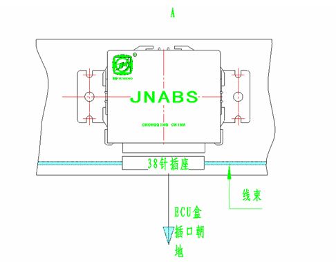
Figure 8 Installation of Electronic Controller ECU
6.5 Installation and debugging of wiring harness and ABS warning light
6.5.1 Installation and debugging of wiring harnesses
Arrange the ABS wire harness shown in the following figure on the car frame. When laying, use a tie every 50 centimeters to firmly secure the wire harness to the frame, and fix the sensor wire to the car brake pipe. Tie it every 20 centimeters (depending on the specific situation).

Figure 9 Typical JN 144 FB harness diagram
Connect the four sensors, left front, right front, left rear, and right rear.
Fasten the circular grounding strap near the negative electrode of the battery.
Connect the A3 and A9 of ECU12 core plug A to the battery+24V through a 15A fuse.
Connect B1 and B14 of ECU26 core plug B to the ignition switch.
Connect B26 of ECU26 core plug B to the retarder (if the vehicle is equipped with a retarder)
Connect ECU12 core plug A and ECU26 core plug B to the ECU.
The three core data interface is reserved for collecting ABS data and using as a fault diagnosis instrument.
The connection of the wire harness should strictly comply with the technical requirements of the Q/JN 0001-1997 standard. The connection between the wire head and the plug connection piece should be tightly pressed with a dedicated crimping tool. The wire harness should be fixed with a tie with the frame or original vehicle cable. During the installation process of the wire harness, special attention should be paid to the direction of the wire harness. The wiring harness should not have any interference with any moving parts on the vehicle. The sensor cables in the wiring harness should be aligned with their corresponding brake pipelines, and the connectors in the wiring harness should be installed in places with good waterproofing as much as possible.
6.5.2 ABS warning light
Install a yellow LED warning light or 2.5W incandescent light at the ABS warning light position on the dashboard in the driver's cab. The high end of the ABS warning light is connected to the ignition switch, while the low end is controlled by the ECU. After turning on the ignition switch, if any equipment installed in the ABS system malfunctions, the ABS light will emit a clear warning flash.
6.6 Inspection and Debugging of ABS System
6.6.1 Check if the fasteners, connectors, and wiring harnesses of each part of the ABS are installed correctly and securely. Whether there is no interference contact with other components. Insert the ECU A and B plugs (12+26 cores) at the front of the harness into the ECU socket.
6.6.2
After turning on the ignition switch, the ABS warning light on the dashboard of the car will stay on for 3 seconds and then automatically turn off. At the same time, the ABS conducts a self check on devices such as the CPU, solenoid valves, and sensors. If the user presses the brake pedal and turns on the ignition switch, they will hear four regular exhaust sounds, indicating that the ABS is in normal working condition. If the ABS warning light flashes, it indicates a malfunction in the ABS system. Follow the instructions in the next section to troubleshoot.
7. JN 1xx FB fault display mode
The fault display of the gathered energy ABS adopts an "automatic single flashing code" fault reporting method, which is characterized by:
When there is a malfunction in the ABS, the reading of the fault code is automatic, and the driver can immediately see the flashing code from the ABS light. After the flashing code is repeated 5 times, it stops flashing for a long time.
The fault code only uses one digit N to indicate the fault location. N=1-8 represents: left front, right front, right rear, left rear, left center 1, right center 1, right center 2, and left center 2. The definition of the fault location is shown in the following figure:

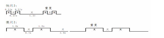
- Use the ABS light to "slow flash" (on for 1 second, off for 0.5 seconds, flashing slowly) to indicate a pressure regulator malfunction. After turning on and off N times, repeat every 3 seconds, which is called "slow flashing N. The flashing code remains on after 5 repetitions, indicating a malfunction.
Use the ABS light to "flash quickly" (on for 0.25 seconds, off for 0.25 seconds, flashing quickly) to indicate faults in the wheel speed sensor and power supply. After turning on and off N times, repeat at an interval of 1.25 seconds, known as "flash N". The flashing code remains on after 5 repetitions, indicating a malfunction.
Taking fast flash 2 and slow flash 2 as examples, the following is the waveform of their on/off time:
- 4-channel or 6-channel ABS uses "flash 7" to indicate power failure (low voltage or fuse failure, etc.), while 8-channel ABS uses "flash 9" to indicate power failure.
After turning on the ignition switch, the ABS light does not flash and remains on, indicating a malfunction in the electronic controller (ECU).
After turning on the ignition switch, the ABS light flashes 5 times and remains on, indicating that a fault stored in the ECU has been read out. This fault must be resolved in order for the ABS to function properly.
After turning on the ignition switch, the ABS light flashes 5 times and then goes out, indicating a fault related to the sensor signal stored in the ECU (excessive gap, etc.). After repair, the repair effect needs to be judged when the vehicle speed is greater than 15Km/h.
8. Fault diagnosis and troubleshooting of JN 1xx FB
The following is a list of ABS fault diagnosis and troubleshooting:
9. ABS fault diagnosis interface and fault diagnosis instrument
The gathered energy ABS has an interface for connecting to the fault diagnosis instrument, which is connected to the ABS fault diagnosis instrument through the DJ7032-2.0-21 three core connector. There are two types of gathered energy ABS fault diagnosis equipment: computer diagnostic equipment and portable diagnostic equipment.
The computer diagnostic instrument can exchange data with the ECU, displaying the fault location and content in graphics and Chinese characters on the computer screen. For example, the left front wheel speed sensor is open circuit, the gap between the right front wheel speed sensor and the gear ring is too large, the right rear isolation solenoid valve is open circuit, the left rear pressure relief solenoid valve is open circuit, and so on. All faults can be displayed. In addition, the computer diagnostic instrument can also receive the speed data of each wheel sent by the ECU, and display it on the computer screen as a wheel speed time curve, which is very accurate for diagnosing wheel speed sensor faults. In addition, it can also be used to analyze the braking effect of ABS and the braking performance of cars without ABS.
Portable diagnostic equipment, like computer diagnostic equipment, can display the fault location and fault content in graphics and Chinese characters on the LCD screen. It can also display all faults, but due to the small LCD screen, only 4 fault contents are displayed on one screen, and the rest are displayed after pressing the "Next" button. In addition, it can also display the speed data of each wheel sent by the ECU, displayed on the LCD screen at xxx Km/h in the front left, xxx Km/h in the front right, xxx Km/h in the rear right, and xxx Km/h in the rear left. These values constantly change while driving a car. If the value of a certain wheel is lower than the value of other wheels, and the error exceeds 10%, the wheel speed value will be replaced with "??", which is very helpful for analyzing faults in the wheel speed sensor.
10. Precautions for using ABS
Before starting, observe whether the ABS fault warning light is displayed normally
10.2 The ABS malfunction warning light flashes under any circumstances, indicating a malfunction in the ABS system. At this time, the ECU will automatically cut off the power supply to the pressure regulator. Make the brake pipeline directly pass through the pressure regulator to reach the brake chamber, maintaining the original brake system. ABS will not function. Due to the lack of ABS, when braking too hard, the wheels will lock up, so you should drive carefully, especially on slippery roads.
10.3 When a car brakes, ABS is involved in the control, which greatly improves the braking stability of the vehicle. However, ABS cannot change the inherent physical conditions of the road (such as changing wet and slippery roads to dry roads, and changing uneven roads to flat roads). Therefore, it is still necessary to drive cautiously and pay attention to safety.
10.4 When driving a car with ABS, do not frequently apply the brakes (jog) when braking in an emergency. Press the brake pedal firmly with one foot.
If there is a malfunction in the ABS system, please contact our company in a timely manner or go to our local repair point for repair.
Attention to users: For the maintenance of JN 1xx FB series products, it is required to replace another component or assembly. Do not change the ABS system status on your own, and do not disassemble or assemble without professional training. Otherwise, all losses that may occur as a result will be borne by the disassembler themselves.
For further details, please contact us
Consultation hotline:+86-13908307100, 13752990427
Office phone:+86 023 63115900, 63115950
Fax:+86-023-67881453
Website: www.jnabs.com
Email: jnabs@jnabs.com
Address: 25th floor, Qibo Building, No. 99 Jinyu Avenue, North New District, Chongqing.